Telematics Control Unit (TCU): Difference between revisions
GeorgeDewar (talk | contribs) No edit summary |
GeorgeDewar (talk | contribs) No edit summary |
||
| (9 intermediate revisions by the same user not shown) | |||
| Line 4: | Line 4: | ||
== Location and access == | == Location and access == | ||
The TCU is located on the right-hand side of the vehicle in all models. | The TCU is located on the right-hand side of the vehicle in all models. It is attached to a metal bracket, which has the [[Around View Monitor Control Unit]] on the other side, if equipped. Once access is achieved, the entire bracket can be removed with the TCU, [[Around View Monitor Control Unit]] and wiring harness all still attached (there's a good amount of slack), and then once pulled forward the TCU can be disconnected. | ||
=== Left-hand drive === | === Left-hand drive === | ||
| Line 12: | Line 12: | ||
=== Right-hand drive === | === Right-hand drive === | ||
The TCU is located above the pedals. | The TCU is located above the pedals. Access is achieved by removing the panel above the pedals, then removing the lower instrument panel (the panel below the steering wheel, with the bonnet release latch and the panel of buttons (open charge door, etc). Refer to the service manual for more detail on removing this panel. | ||
== Variants == | == Variants == | ||
=== 2G === | === 2G === | ||
Known part numbers: | |||
* 283B0 3NM0A | * 283B0 3NM0A | ||
| Line 25: | Line 25: | ||
=== 4G === | === 4G === | ||
Known part numbers: | |||
* 28275 5SA0A | |||
* 28275 5SA0B | * 28275 5SA0B | ||
* 28275 5ZA0D | * 28275 5ZA0D | ||
* 28275 6FL0B | |||
These are found on some 2nd-generation Nissan Leafs. | These are found on some 2nd-generation Nissan Leafs. The one pictured below (p/n 28275 5SA0B) includes a Sierra Wireless AirPrime AR7554 modem module, a chip labelled R7F7010259 (possibly part of the Renesas RH850/F1L family), a small PIC16LF1518 chip, an A1051/3 CAN transceiver chip, an A1043 CAN interface chip (this list is not exhaustive). An examination and probe of the board while powered on did not reveal any obvious UART terminals, however it does emit CAN data while powered on on a bench. | ||
It does not contain a physical SIM slot. | It does not contain a physical SIM slot. | ||
The unit photographed below is not detected as a USB device when connected to a computer. It may be faulty, or in some kind of disabled mode, or a non-standard USB protocol, I am not sure. | |||
In vehicles which have had an English conversion done by EVs Enhanced, the [[AV Control Unit]] may not function while the TCU is disconnected (complaining about a missing or invalid key file). | |||
<gallery widths="160" heights="160"> | <gallery widths="160" heights="160"> | ||
| Line 47: | Line 53: | ||
!Purpose | !Purpose | ||
|- | |- | ||
|M67 | |[[M67]] | ||
|TH40FB-NH (40-pin connector) | |TH40FB-NH (40-pin connector) | ||
{| class="wikitable" | {| class="wikitable" | ||
|- | |- | ||
|[[File: | |[[File:CTH40F05HS.svg|frameless]] | ||
|} | |} | ||
|Power, Microphone, CANBUS ([[IT-CAN]] and [[M-CAN]]) | |Power, Microphone, CANBUS ([[IT-CAN]] and [[M-CAN]]) | ||
|- | |- | ||
|M173 | |[[M173]] | ||
|USCAR30-MD-M (USB) | |USCAR30-MD-M (USB) | ||
|USB connection to [[AV Control Unit]] | |USB connection to [[AV Control Unit]] | ||
|- | |- | ||
|M174 | |[[M174]] | ||
|FAKRA CODE H 4003 (Pink) | |FAKRA CODE H 4003 (Pink) | ||
|GSM antenna | |GSM antenna | ||
|- | |- | ||
|M175 | |[[M175]] | ||
|3FA1ANCSJ-C02W0 (Blue) | |3FA1ANCSJ-C02W0 (Blue) | ||
|GPS antenna | |GPS antenna | ||
|} | |} | ||
==== M67 | ==== M67 ([[NAM]]) ==== | ||
{{:M67}} | |||
==== M173 ==== | |||
{{:M173}} | |||
==== M174 ==== | |||
{{:M174}} | |||
==== M175 ==== | |||
{{:M175}} | |||
=== 5G === | === 5G === | ||
Latest revision as of 09:58, 27 April 2025
The Telematics Control Unit (TCU) provides connectivity to the Nissan Leaf. It is a 2G, 3G, 4G or 5G modem, depending on the year and region, with additional functionality. The TCU provides internet connectivity to the AV Control Unit via USB, while also communicating with Nissan's servers in its own right to provide CarWings / Nissan Connect functionality such as remote climate control.

Location and access
The TCU is located on the right-hand side of the vehicle in all models. It is attached to a metal bracket, which has the Around View Monitor Control Unit on the other side, if equipped. Once access is achieved, the entire bracket can be removed with the TCU, Around View Monitor Control Unit and wiring harness all still attached (there's a good amount of slack), and then once pulled forward the TCU can be disconnected.
Left-hand drive
The TCU is located behind the glove box. Access is achieved by removing the glove box.
Right-hand drive
The TCU is located above the pedals. Access is achieved by removing the panel above the pedals, then removing the lower instrument panel (the panel below the steering wheel, with the bonnet release latch and the panel of buttons (open charge door, etc). Refer to the service manual for more detail on removing this panel.
Variants
2G
Known part numbers:
- 283B0 3NM0A
3G
4G
Known part numbers:
- 28275 5SA0A
- 28275 5SA0B
- 28275 5ZA0D
- 28275 6FL0B
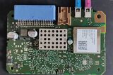
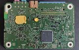
These are found on some 2nd-generation Nissan Leafs. The one pictured below (p/n 28275 5SA0B) includes a Sierra Wireless AirPrime AR7554 modem module, a chip labelled R7F7010259 (possibly part of the Renesas RH850/F1L family), a small PIC16LF1518 chip, an A1051/3 CAN transceiver chip, an A1043 CAN interface chip (this list is not exhaustive). An examination and probe of the board while powered on did not reveal any obvious UART terminals, however it does emit CAN data while powered on on a bench.
It does not contain a physical SIM slot.
The unit photographed below is not detected as a USB device when connected to a computer. It may be faulty, or in some kind of disabled mode, or a non-standard USB protocol, I am not sure.
In vehicles which have had an English conversion done by EVs Enhanced, the AV Control Unit may not function while the TCU is disconnected (complaining about a missing or invalid key file).
-
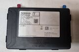 External view
 -
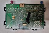 Circuit board side A
 -
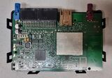 Circuit board side B


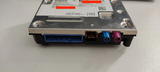
Connections
| Connector Number | Physical Description | Purpose | |
|---|---|---|---|
| M67 | TH40FB-NH (40-pin connector)
|
Power, Microphone, CANBUS (IT-CAN and M-CAN) | |
| M173 | USCAR30-MD-M (USB) | USB connection to AV Control Unit | |
| M174 | FAKRA CODE H 4003 (Pink) | GSM antenna | |
| M175 | 3FA1ANCSJ-C02W0 (Blue) | GPS antenna |

M67 (NAM)
| Pin No. | Color of Wire | Signal Name |
|---|---|---|
| 1 | White |
+Vbat |
| 2 | Red |
Acc (without BOSE Audio System) |
| 2 | Yellow |
Acc (with BOSE Audio System) |
| 3 | Brown |
Acc Out |
| 4 | - | - |
| 5 | Lavender / Blue |
LED Green |
| 6 | Sky Blue |
CAN-H |
| 7 | Violet |
CAN-L |
| 8 | - | - |
| 9 | - | - |
| 10 | Green |
Wake Up/Ign |
| 11 | Shield |
Mic Out Gnd |
| 12 | Blue |
Mic Out Signal |
| 13 | - | - |
| 14 | - | - |
| 15 | - | - |
| 16 | Shield |
Mic Gnd |
| 17 | Blue |
Mic Signal |
| 18 | Pink |
Mic Vcc |
| 19 | - | - |
| 20 | - | - |
| 21 | - | - |
| 22 | - | - |
| 23 | - | - |
| 24 | - | - |
| 25 | - | - |
| 26 | Sky Blue |
M CAN-H |
| 27 | Light Green |
M CAN-L |
| 28 | Black |
Gnd |
| 29 | Black |
Gnd |
| 30 | - | - |
| 31 | Green |
Audio Hu Out+ |
| 32 | Red |
Audio Hu Out- |
| 33 | - | - |
| 34 | - | - |
| 35 | - | - |
| 36 | - | - |
| 37 | Lavender / Yellow |
Ecall Sw |
| 38 | - | - |
| 39 | - | - |
| 40 | - | - |
M173
| Pin No. | Color of Wire | Signal Name |
|---|---|---|
| 41 | Black |
Gnd |
| 42 | - | - |
| 43 | Green |
D+ |
| 44 | White |
D- |
| 45 | Red |
Vbus |
| 46 | Shield |
Shield |
M174
| Pin No. | Color of Wire | Signal Name |
|---|---|---|
| 47 | Black |
Gsm Ant |
| 48 | Shield |
Gsm Shield |
M175
| Pin No. | Color of Wire | Signal Name |
|---|---|---|
| 49 | Black |
GPS Ant |
| 50 | Shield |
GPS Shield |
5G
Part numbers:
- 28275 6HL9B
-
 External view
 -
 Circuit board side A
 -
 Circuit board side B


Open-source Telematics
Owners who cannot use Nissan Connect (e.g. because it is not offered in their country), or don't want to use it, have a couple of options.
OVMS is an open-source module that can provide all sorts of telematics functionality such as GPS positioning, remote climate control, remote lock/unlock, battery monitoring, etc. In Gen 1 Leafs it can be installed via a simple plug into the OBDII port. In Gen 2 Leafs, a custom adaptor cable can be made to tap into the power and CAN buses at the CAN Gateway.[1] It is also necessary to disable the TCU, either by disconnecting the CAN BUS wires on its connector, or by removing it completely and replacing it with a couple of bridging wires and a 5V regulator to keep the AV Control Unit powered, power the microphone and pass its signal through.
For 2G TCUs, it is possible to replace the SIM and configure the TCU to connect to a server of one's choosing.[2]
External Links
- Reverse engineering Telematics Unit - My Nissan Leaf Forum
- (2018+) TCU Decoding and Emulating - My Nissan Leaf Forum
- https://github.com/developerfromjokela/nissan-leaf-tcu
- DEF CON 25 - Mickey Shkatov, Jesse Michael, Oleksandr Bazhaniuk - Driving down the rabbit hole - YouTube